THE CATAPULT This spindle passes through the center of the roller and through the sides of the frame. The small cogged wheels, with their checks, which are fitted to the ends of the spindle GG, prevent the roller from reversing as the arm is being wound down. (Fig. 6.) HH. The hollows in the sides of the frame which receive the lower tenons of the two uprights. Between the tops of these uprights the cross-beam is fixed against which the arm of the catapult strikes when it is released. (Fig. 6.) KK. The hollows for the lower tenons of the two sloping supports which prevent the uprights, and the cross-beam between them, from giving way when the arm recoils. (Fig. 6.)
I. Surface view of one of the winches and of the thick iron plate in which the socket of the large winding wheel of the winch revolves. II. View of a winch (from above) as fitted into one of the sides of the frame of the catapult. One end of the twisted skein may be seen turned round the cross- bar of the large wheel. III. Side view of the large wheel of a winch. IV. The cross-bar of one of the large wheels. These pieces fit like wedges into tapering slots cut down the barrels, or inside surfaces, of their respective wheels. V. Perspective view of the wheels of a winch. The winches are the vital parts of the catapult as they generate its projectile power. 17 THE CATAPULT They are employed to twist tightly the skein of cord between which the butt-end of the arm of the engine is placed. The cord composing the skein is stretched to and fro across and through the sides of the catapult, and alternately through the insides of the large wheels and over their cross-bars ; as show in fig. 8. 
FIG. 10. THE IRON SLIP HOOK This simple contrivance not only pulled down the arm of a catapult but was also the means of setting it free. However great the strain on the slip-hook, it will, if properly shaped, easily effect the release of the arm. The trajectory of the missile can be regulated by this form of release, as the longer the distance the arm is pulled down the higher the angle at which the projectile is thrown. On the other hand, the shorter the distance the arm is drawn back, the lower the trajectory of its missile. The slip-hook will release the arm of the engine at any moment, whether it is fully or only partially wound down by the windlass. The slip-hook of the large catapult shown in fig. 6. , has a handle, i.e. lever, 10 inches long, the point of the hook, which passes through the eye-bolt secured to the arm, being one inch in diameter.
18 THE CATAPULT
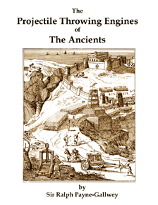
A. The skein as first wound over the cross-bars of the large wheels (shown in section) of the winches. B. The skein with the butt-end of the arm (shown in section) placed between its halves. C. The skein as it appears when tightly twisted up by the winches. Compare with AA, fig. 8. Cord of Italian hemp, about . in. thick, is excellent for small catapults. For large ones, horsehair rope, . in. thick, is the best and most elastic. Whatever is used, the material of the skein must be thoroughly soaked in neats-foot oil for some days previously, or it is sure to fray and cut under the friction of being very tightly twisted. Oil will also preserve the skein from damp and decay for many years. HOW TO WORK THE CATAPULT There is little to write under this heading ; as the plans, details of construction and illustrations will, I trust, elucidate its management. The skein should never remain in a tightly twisted condition, but should be untwisted when the engine is not in use. Previous to using the catapult its winches should be turned with the long spanner, fig. 6, first the winch on one side of the engine and then the one on the other side of it, and each to exactly the same amount. Small numerals painted on the surfaces of the large wheels near their 19 THE CATAPULT edges, will show how much they have been revolved ; in this way their rotation can be easily arranged to correspond. As the skein of cord is being twisted by the very powerful winches, the arm will gradually press with increasing force against the cross-beam between the uprights. The arm should be so tightly pressed against the fender, or cushion of straw, attached to the centre of this beam, that, whether large or small, it cannot be pulled back the least distance by hand. If the skein of my largest catapult is fully tightened up by the winches, three strong men are unable to draw the arm back with a rope even an inch from the cross-beam, though the windlass has to pull it down from six to seven feet when the engine is made ready for action. When the skein is as tight as it should be, attach the slip-hook to the ring- bolt in the arm and place the stone in the sling suspended from the top of the arm. The arm can now be drawn down by means of long spanners fitted to the windlass. Directly the arm is as low as it should be, or as is desired, it should be instantly released by pulling the cord fastened to the lever of the slip-hook. The least delay in doing this, and the resulting continuation of the immense strain on the arm, may cause it to fracture when it would not otherwise have done so. The plans I have given are those of my largest engine, which, ponderous as it seems(it weighs two tons)is, however, less than half the size of the catapult used by the ancients for throwing stones of from forty to fifty pounds in weight. As the plans are accurately drawn to scale, the engine can easily be reproduced in a smaller size. An interesting model can be constructed that has an arm 3 feet in length, and a skein of cord about 4 inches in diameter. It can be worked by one man and will throw a stone, the size of an orange, to a range of 300 yards. The sling, when suspended with the stone in position, should be one third the length of the arm, as shown in fig. 7 . If the sling is shortened, the ball will be thrown at a high elevation. If the sling is lengthened, the ball will travel at a lower angle and with much more velocity. 20 The Projectile Throwing Engines of The Ancients Design, Construction and Operation of Ancient Greek, Roman and Medieval Siege Engines and Their Effects In Warfare
Written by Sir Ralph Payne-Gallwey in 1907,this is the first serious modern work on ancient siege engines and the early history of artillery. In this book, Payne-Gallwey first cites the ancient writings of Greeks and Romans on sieges and the associated artillery. In order to test the validity of the ancient accounts, he produces his own full size working versions of these ancient machines and tests the construction and performance claims of the ancient writers. Fully illustrated, this book gives extensive details about the design, construction, operation and performance of the three types of siege engines: the Catapult (both the Mangonel and Onager), the Ballista and the Trebuchet.
Free Plans to Make a Catapult - Make a Catapult from Free Plans
|
|||||||||||||||||||||||||||||||||||||||||||||||||||||||||||||||||||||||||||||||||||||||||||||||||||||||||||||||||||||||||||||||||||||||||||||||||||||||||||||||||||||||