|
The Crossbow
Chapter XXXI
The Cranequin, and How It was Applied to Bend the
Steel Bow of a Crossbow
A, fig. 90, p. 138. The surface view of the working parts of a cranequin,
its casing being omitted. The claws of the ratchet bar are to be seen hooked
over the bow-string.
B, fig. 90. The side view of the cranequin with its parts fitted, the
casing being shown in section only.
C, fig. 90. The small spindle which is secured to and turned by the
handle of the cranequin.
D, fig. 90. The side view of the large wheel.
E, fig. 90. The small wheel, with its three thick cogs. This wheel is
part of the large wheel D, both wheels being made of one solid piece.
F, fig. 90. The strong metal ring that holds the thick cord loop which
is placed over the stock of the crossbow when the cranequin is about to
be used The under side of this metal ring rests upon the top of the crossbow
when the cranequin is in position for bending the bow. The ring is fixed
below the centre of the left half of the casing, underneath the ratchet
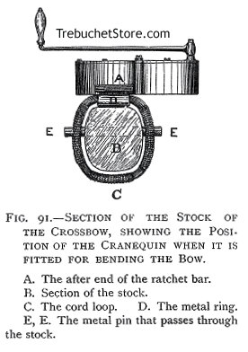
bar, D, fig. 91.

Fig. 91. - Section of the Stock of the Crossbow, Showing
the Position of the Cranequin when It is Fitted for Bending the Bow.
A. The after end of the ratchet bar.
B. Section of the Stock.
C. The Cord Loop. D. The metal ring.
E, E. The metal pin that passes through the stock.
This position of the metal ring, causes the cord loop and the ratchet
bar and its claws, to jointly take the great strain of the bending bow
in line with the stock of the crossbow, fig. 93, p. 143.
If the ring which holds the cord loop was fixed beneath the centre of
the |